Product Description
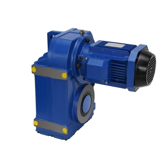
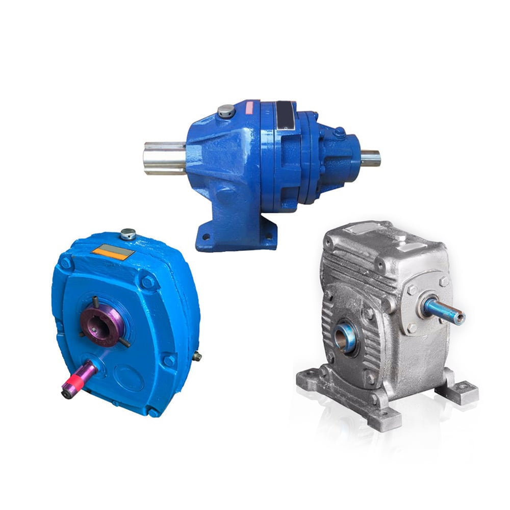
Starshine Drive K Series Helical -Bevel Geared Motor
Features:
-High efficiency: 92%-93%;
-Vertical output, compact structure, hard tooth surface , large output torque, low noise and long service life.
-High precision: the gear is made of high-quality alloy steel forging, carbonitriding and hardening treatment, grinding process to ensure high precision and stable running.
-High interchangeability: highly modular, serial design, strong versatility and interchangeability.
Technical parameters
| Ratio | 5.36-197.37 |
| Input power | 0.12-200KW |
| Output torque | 10-62800N.m |
| Output speed | 7-415rpm |
| Mounting type | Foot mounted, foot mounted with CZPT shaft, output flange mounted, hollow shaft mounted, B5 flange mounted with hollow shaft, foot mounted with hollow shaft, B14 flange mounted with hollow shaft, foot mounted with splined hole, foot mounted with shrink disk, hollow shaft mounted with anti-torque arm. |
| Input Method | Flange input(AM), shaft input(AD), inline AC motor input, or AQA servo motor |
| Brake Release | HF-manual release(lock in the brake release position), HR-manual release(autom-atic braking position) |
| Thermistor | TF(Thermistor protection PTC thermisto) TH(Thermistor protection Bimetal swotch) |
ABOUT CZPT DRIVE
ZheJiang CZPT Drive Co.,Ltd(Starshine) have a strong technical force with over 350 employees at present, including over 30 engineering technicians, 30 quality inspectors, covering an area of 80000 square CZPT and kinds of advanced processing machines and testing equipments. We have a good foundation for the industry application development and service of high-end speed reducers & variators owning to the provincial engineering technology research center,the lab of gear speed reducers, and the base of modern R&D.
Our products are widely used in ceramic industry, glass industry, woodworking machinery , high voltage switch, food & beverage, packaging & printing, Storage & logistics, hoisting & transportation facilities…etc , and CZPT technically provide the professional product & service for the medium and high-end customers, and our gearboxes are best-selling in domestic, and even in abroad , such as in Europe, North America, South America, Middle East, South Asia, Southeast Asia, Africa…etc.
In the future , CZPT will hold the creed of “serving customer, diligence & simplicity, self-criticism, innovation, honesty, teamwork”, and the concept of “quality creates value” to focus on the customers’ requirements and provide them the competitive transmission solution and create value for them constantly, and make a high-end equipment manufacturing industry and create a preferred brand of replacing import products and upgrading continuously for the end users.
TEAM
QUALITY CONTROL
Quality:Insist on Improvement,Strive for CZPT With the development of equipment manufacturing indurstry,customer never satirsfy with the current quality of our products,on the contrary,wcreate the value of quality.
Quality policy:to enhance the overall level in the field of power transmission
Quality View:Continuous Improvement , pursuit of excellence
Quality Philosophy:Quality creates value
3. Incoming Quality Control
To establish the AQL acceptable level of incoming material control, to provide the material for the whole inspection, sampling, immunity. On the acceptance of qualified products to warehousing, substandard goods to take return, check, rework, rework inspection; responsible for tracking bad, to monitor the supplier to take corrective measures to prevent recurrence.
4. Process Quality Control
The manufacturing site of the first examination, inspection and final inspection, sampling according to the requirements of some projects, judging the quality change trend; found abnormal phenomenon of manufacturing, and supervise the production department to improve, eliminate the abnormal phenomenon or state
5. FQC(Final QC)
After the manufacturing department will complete the product, stand in the customer’s position on the finished product quality verification, in order to ensure the quality of customer expectations and needs.
6. OQC(Outgoing QC)
After the product sample inspection to determine the qualified, allowing storage, but when the finished product from the warehouse before the formal delivery of the goods, there is a check, this is called the shipment inspection.Check content:In the warehouse storage and transfer status to confirm, while confirming the delivery of the product is a product inspection to determine the qualified products.
PACKING
DELIVERY
| Application: | Motor, Machinery, Agricultural Machinery |
|---|---|
| Function: | Distribution Power, Change Drive Torque, Change Drive Direction, Speed Changing, Speed Reduction |
| Layout: | Corner |
| Hardness: | Hardened Tooth Surface |
| Installation: | Horizontal Type |
| Step: | Three-Step |
| Customization: |
Available
| Customized Request |
|---|

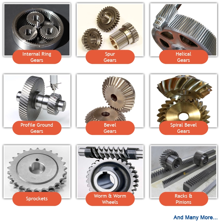
Helical, Straight-Cut, and Spiral-Bevel Gears
If you are planning to use bevel gears in your machine, you need to understand the differences between Helical, Straight-cut, and Spiral bevel gears. This article will introduce you to these gears, as well as their applications. The article will also discuss the benefits and disadvantages of each type of bevel gear. Once you know the differences, you can choose the right gear for your machine. It is easy to learn about spiral bevel gears.
Spiral bevel gear
Spiral bevel gears play a critical role in the aeronautical transmission system. Their failure can cause devastating accidents. Therefore, accurate detection and fault analysis are necessary for maximizing gear system efficiency. This article will discuss the role of computer aided tooth contact analysis in fault detection and meshing pinion position errors. You can use this method to detect problems in spiral bevel gears. Further, you will learn about its application in other transmission systems.
Spiral bevel gears are designed to mesh the gear teeth more slowly and appropriately. Compared to straight bevel gears, spiral bevel gears are less expensive to manufacture with CNC machining. Spiral bevel gears have a wide range of applications and can even be used to reduce the size of drive shafts and bearings. There are many advantages to spiral bevel gears, but most of them are low-cost.
This type of bevel gear has three basic elements: the pinion-gear pair, the load machine, and the output shaft. Each of these is in torsion. Torsional stiffness accounts for the elasticity of the system. Spiral bevel gears are ideal for applications requiring tight backlash monitoring and high-speed operations. CZPT precision machining and adjustable locknuts reduce backlash and allow for precise adjustments. This reduces maintenance and maximizes drive lifespan.
Spiral bevel gears are useful for both high-speed and low-speed applications. High-speed applications require spiral bevel gears for maximum efficiency and speed. They are also ideal for high-speed and high torque, as they can reduce rpm without affecting the vehicle’s speed. They are also great for transferring power between two shafts. Spiral bevel gears are widely used in automotive gears, construction equipment, and a variety of industrial applications.
Hypoid bevel gear
The Hypoid bevel gear is similar to the spiral bevel gear but differs in the shape of the teeth and pinion. The smallest ratio would result in the lowest gear reduction. A Hypoid bevel gear is very durable and efficient. It can be used in confined spaces and weighs less than an equivalent cylindrical gear. It is also a popular choice for high-torque applications. The Hypoid bevel gear is a good choice for applications requiring a high level of speed and torque.
The Hypoid bevel gear has multiple teeth that mesh with each other at the same time. Because of this, the gear transmits torque with very little noise. This allows it to transfer a higher torque with less noise. However, it must be noted that a Hypoid bevel gear is usually more expensive than a spiral bevel gear. The cost of a Hypoid bevel gear is higher, but its benefits make it a popular choice for some applications.
A Hypoid bevel gear can be made of several types. They may differ in the number of teeth and their spiral angles. In general, the smaller hypoid gear has a larger pinion than its counterpart. This means that the hypoid gear is more efficient and stronger than its bevel cousin. It can even be nearly silent if it is well lubricated. Once you’ve made the decision to get a Hypoid bevel gear, be sure to read up on its benefits.
Another common application for a Hypoid bevel gear is in automobiles. These gears are commonly used in the differential in automobiles and trucks. The torque transfer characteristics of the Hypoid gear system make it an excellent choice for many applications. In addition to maximizing efficiency, Hypoid gears also provide smoothness and efficiency. While some people may argue that a spiral bevel gear set is better, this is not an ideal solution for most automobile assemblies.
Helical bevel gear
Compared to helical worm gears, helical bevel gears have a small, compact housing and are structurally optimized. They can be mounted in various ways and feature double chamber shaft seals. In addition, the diameter of the shaft and flange of a helical bevel gear is comparable to that of a worm gear. The gear box of a helical bevel gear unit can be as small as 1.6 inches, or as large as eight cubic feet.
The main characteristic of helical bevel gears is that the teeth on the driver gear are twisted to the left and the helical arc gears have a similar design. In addition to the backlash, the teeth of bevel gears are twisted in a clockwise and counterclockwise direction, depending on the number of helical bevels in the bevel. It is important to note that the tooth contact of a helical bevel gear will be reduced by about ten to twenty percent if there is no offset between the two gears.
In order to create a helical bevel gear, you need to first define the gear and shaft geometry. Once the geometry has been defined, you can proceed to add bosses and perforations. Then, specify the X-Y plane for both the gear and the shaft. Then, the cross section of the gear will be the basis for the solid created after revolution around the X-axis. This way, you can make sure that your gear will be compatible with the pinion.
The development of CNC machines and additive manufacturing processes has greatly simplified the manufacturing process for helical bevel gears. Today, it is possible to design an unlimited number of bevel gear geometry using high-tech machinery. By utilizing the kinematics of a CNC machine center, you can create an unlimited number of gears with the perfect geometry. In the process, you can make both helical bevel gears and spiral bevel gears.
Straight-cut bevel gear
A straight-cut bevel gear is the easiest to manufacture. The first method of manufacturing a straight bevel gear was to use a planer with an indexing head. Later, more efficient methods of manufacturing straight bevel gears were introduced, such as the Revacycle system and the Coniflex system. The latter method is used by CZPT. Here are some of the main benefits of using a straight-cut bevel gear.
A straight-cut bevel gear is defined by its teeth that intersect at the axis of the gear when extended. Straight-cut bevel gears are usually tapered in thickness, with the outer part being larger than the inner portion. Straight-cut bevel gears exhibit instantaneous lines of contact, and are best suited for low-speed, static-load applications. A common application for straight-cut bevel gears is in the differential systems of automobiles.
After being machined, straight-cut bevel gears undergo heat treatment. Case carburizing produces gears with surfaces of 60-63 Rc. Using this method, the pinion is 3 Rc harder than the gear to equalize wear. Flare hardening, flame hardening, and induction hardening methods are rarely used. Finish machining includes turning the outer and inner diameters and special machining processes.
The teeth of a straight-cut bevel gear experience impact and shock loading. Because the teeth of both gears come into contact abruptly, this leads to excessive noise and vibration. The latter limits the speed and power transmission capacity of the gear. On the other hand, a spiral-cut bevel gear experiences gradual but less-destructive loading. It can be used for high-speed applications, but it should be noted that a spiral-cut bevel gear is more complicated to manufacture.
Spur-cut bevel gear
CZPT stocks bevel gears in spiral and straight tooth configurations, in a range of ratios from 1.5 to five. They are also highly remachinable except for the teeth. Spiral bevel gears have a low helix angle and excellent precision properties. CZPT stock bevel gears are manufactured using state-of-the-art technologies and know-how. Compared with spur-cut gears, these have a longer life span.
To determine the strength and durability of a spur-cut bevel gear, you can calculate its MA (mechanical advantage), surface durability (SD), and tooth number (Nb). These values will vary depending on the design and application environment. You can consult the corresponding guides, white papers, and technical specifications to find the best gear for your needs. In addition, CZPT offers a Supplier Discovery Platform that allows you to discover more than 500,000 suppliers.
Another type of spur gear is the double helical gear. It has both left-hand and right-hand helical teeth. This design balances thrust forces and provides extra gear shear area. Helical gears, on the other hand, feature spiral-cut teeth. While both types of gears may generate significant noise and vibration, helical gears are more efficient for high-speed applications. Spur-cut bevel gears may also cause similar effects.
In addition to diametral pitch, the addendum and dedendum have other important properties. The dedendum is the depth of the teeth below the pitch circle. This diameter is the key to determining the center distance between two spur gears. The radius of each pitch circle is equal to the entire depth of the spur gear. Spur gears often use the addendum and dedendum angles to describe the teeth.


editor by CX 2023-05-29
China wholesaler R58 1.5HP/CV 1.1kw Helical Gear Motor Reduction Motor supplier
Product Description
Product Description
Product Description
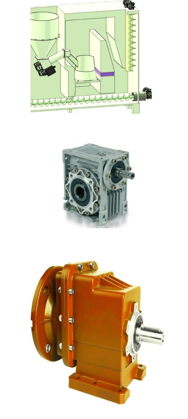
-R Series Helical gearbox
Product Features:
1.High modular design.
2.Integrated casting housing,compact dimension,high loading support, stable transmitting and low noise level.
3.Perfect oil leakage preventing makes the good sealings and can be used in wide range of industry.
4.This series is special for pug mill.
5.High efficiency and save power.
6.Save cost and low maintenance.
Design Features:
1. Compact structure, modular design
2. Single-stage, two-stage and three-stage sizes
3. Can be combined with other types of gearboxes (Such as R Series, K Series, F Series, S Series, UDL Series)
Product Parameters
1 Stage
| Models | Output Shaft Dia. | Input Shaft Dia. | Power(kW) | Ratio | Max. Torque(Nm) |
| BRX/BRXF38 | 20mm | 16mm | 0.18~1.1 | 1.62~4.43 | 20 |
| BRX/BRXF58 | 20mm | 19mm | 0.18~5.5 | 1.3~5.5 | 70 |
| BRX/BRXF68 | 25mm | 19mm | 0.18~7.5 | 1.4~6.07 | 135 |
| BRX/BRXF78 | 30mm | 24mm | 1.1~11 | 1.42~8.00 | 215 |
| BRX/BRXF88 | 40mm | 28mm | 3~22 | 1.39~8.65 | 400 |
| BRX/BRXF98 | 50mm | 38mm | 5.5~30 | 1.42~8.23 | 600 |
| BRX/BRXF108 | 60mm | 42mm | 7.5~45 | 1.44~6.63 | 830 |
| BRX/BRXF128 | 75mm | 55mm | 7.5~90 | 1.51~6.2 | 1110 |
| BRX/BRXF158 | 90mm | 70mm | 11~132 | 1.57~6.2 | 1680 |
2-3Stage
| Models | Output Shaft Dia. | Input Shaft Dia. | Power(kW) | Ratio | Max. Torque(Nm) |
| BR/BRF18 | 20mm | – | 0.18~0.75 | 3.83~74.84 | 85 |
| BR/BRF28 | 25mm | 16mm | 0.18~3 | 3.37~135.09 | 130 |
| BR/BRF38 | 25mm | 16mm | 0.18~3 | 3.41~134.82 | 200 |
| BR/BRF48 | 30mm | 19mm | 0.18~5.5 | 3.83~176.88 | 300 |
| BR/BRF58 | 35mm | 19mm | 0.18~7.5 | 4.39~186.89 | 450 |
| BR/BRF68 | 35mm | 19mm | 0.18~7.5 | 4.29~199.81 | 600 |
| BR/BRF78 | 40mm | 24mm | 0.18~11 | 5.21~195.24 | 820 |
| BR/BRF88 | 50mm | 28mm | 0.55~18.5 | 5.36~246.54 | 1550 |
| BR/BRF98 | 60mm | 38mm | 0.55~30 | 4.49~289.6 | 3000 |
| BR/BRF108 | 70mm | 42mm | 2.2~45 | 5.06~249.16 | 4300 |
| BR/BRF138 | 90mm | 55mm | 5.5~55 | 5.51~222.6 | 8000 |
| BR/BRF148 | 110mm | 55mm | 11~90 | 5.00~163.31 | 13000 |
| BR/BRF168 | 120mm | 70mm | 11~160 | 8.77~229.71 | 18000 |
Materials Data Sheet
|
Housing material |
Grey Cast iron |
|
Housing hardness |
HBS163~255 |
|
Gear material |
20CrMnTi alloy steel |
|
Surface hardness of gears |
HRC58°~62 ° |
|
Gear core hardness |
HRC33~48 |
|
Input / Output shaft material |
40Cr alloy steel |
|
Input / Output shaft hardness |
HRC32~36 |
|
Machining precision of gears |
accurate grinding, 6~5 Grade |
|
Lubricating oil |
GB L-CKC220-460, Shell Omala220-460 |
|
Heat treatment |
tempering, cementiting, quenching, normalizing, etc. |
|
Efficiency |
94%~96% (depends on the transmission stage) |
|
Noise (MAX) |
60~68dB |
|
Temp. rise (MAX) |
40°C |
|
Temp. rise (Oil)(MAX) |
50°C |
|
Vibration |
≤20µm |
|
Backlash |
≤20Arcmin |
|
Brand of bearings |
China top brand bearing, HRB/LYC/ZWZ/C&U. Or other brands requested, SKF, FAG, INA, NSK. |
|
Brand of oil seal |
NAK — ZheJiang or other brands requested |
Detailed Photos
Our process of production
Our product line
Company Profile
Company Profile
Bode was founded in 2007, which is located in HangZhou city, ZHangZhoug province. As 1 professional manufacturer and exporter, we have more than 17 years’ experience in R & D of worm reducer, gear reducer, gearbox , AC motor and relative spare parts. We have factory with advanced production and test equipment, the strong development of team and producing capacity offer our customers with high quality products. Our products widely served to various industries of Metallurgy, Chemicals, lifting, mining, Petroleum, textile, medicine, wooden etc. Main markets: China, Africa, Australia, Vietnam, Turkey, Japan, Korea, Philippines… Welcome to ask us any questions, good offer always for you for long term business.
FAQ
Q1: Are you trading company or manufacturer?
A: We are factory.
Q2: What kinds of gearbox can you produce for us?
A: Main products of our company: R, S, K, F series helical-tooth reducer, RV series worm gear reducer,H Series Parallel Shaft Helical Reduction Gear Box
Q3: Can you make as per custom drawing?
A: Yes, we offer customized service for customers.
Q4: Can we buy 1 pc of each item for quality testing?
A: Yes, we are glad to accept trial order for quality testing.
Q5: What information shall we give before placing a purchase order?
A: a) Type of the gearbox, ratio, input and output type, input flange, mounting position, and motor informationetc.
b) Housing color.
c) Purchase quantity.
d) Other special requirements.
Q6: How long is your delivery time?
A: Generally it is 5-10 days if the goods are in stock. or it is 15-20 days if the goods are not in stock.
Q7: What is your terms of payment ?
A: 30% Advance payment by T/T after signing the contract.70% before delivery
If you are interested in our product, welcome to contact with us.
Our team will do our best to meet your need 🙂
| Application: | Machinery, Marine, Agricultural Machinery |
|---|---|
| Function: | Distribution Power, Change Drive Torque, Speed Changing, Speed Reduction |
| Layout: | Coaxial |
| Hardness: | Hardened Tooth Surface |
| Installation: | Vertical Type |
| Step: | Single-Step |
| Samples: |
US$ 50/Piece
1 Piece(Min.Order) | |
|---|
| Customization: |
Available
| Customized Request |
|---|

Synthesis of Epicyclic Gear Trains for Automotive Automatic Transmissions
In this article, we will discuss the synthesis of epicyclic gear trains for automotive automatic transmissions, their applications, and cost. After you have finished reading, you may want to do some research on the technology yourself. Here are some links to further reading on this topic. They also include an application in hybrid vehicle transmissions. Let’s look at the basic concepts of epicyclic gear trains. They are highly efficient and are a promising alternative to conventional gearing systems.
Synthesis of epicyclic gear trains for automotive automatic transmissions
The main purpose of automotive automatic transmissions is to maintain engine-drive wheel balance. The kinematic structure of epicyclic gear trains (EGTs) is derived from graph representations of these gear trains. The synthesis process is based on an algorithm that generates admissible epicyclic gear trains with up to ten links. This algorithm enables designers to design auto gear trains that have higher performance and better engine-drive wheel balance.
In this paper, we present a MATLAB optimization technique for determining the gear ratios of epicyclic transmission mechanisms. We also enumerate the number of teeth for all gears. Then, we estimate the overall velocity ratios of the obtained EGTs. Then, we analyze the feasibility of the proposed epicyclic gear trains for automotive automatic transmissions by comparing their structural characteristics.
A six-link epicyclic gear train is depicted in the following functional diagram. Each link is represented by a double-bicolor graph. The numbers on the graph represent the corresponding links. Each link has multiple joints. This makes it possible for a user to generate different configurations for each EGT. The numbers on the different graphs have different meanings, and the same applies to the double-bicolor figure.
In the next chapter of this article, we discuss the synthesis of epicyclic gear trains for automotive automatic transaxles. SAE International is an international organization of engineers and technical experts with core competencies in aerospace and automotive. Its charitable arm, the SAE Foundation, supports many programs and initiatives. These include the Collegiate Design Series and A World In Motion(r) and the SAE Foundation’s A World in Motion(r) award.
Applications
The epicyclic gear system is a type of planetary gear train. It can achieve a great speed reduction in a small space. In cars, epicyclic gear trains are often used for the automatic transmission. These gear trains are also useful in hoists and pulley blocks. They have many applications in both mechanical and electrical engineering. They can be used for high-speed transmission and require less space than other types of gear trains.
The advantages of an epicyclic gear train include its compact structure, low weight, and high power density. However, they are not without disadvantages. Gear losses in epicyclic gear trains are a result of friction between gear tooth surfaces, churning of lubricating oil, and the friction between shaft support bearings and sprockets. This loss of power is called latent power, and previous research has demonstrated that this loss is tremendous.
The epicyclic gear train is commonly used for high-speed transmissions, but it also has a small footprint and is suitable for a variety of applications. It is used as differential gears in speed frames, to drive bobbins, and for the Roper positive let-off in looms. In addition, it is easy to fabricate, making it an excellent choice for a variety of industrial settings.
Another example of an epicyclic gear train is the planetary gear train. It consists of two gears with a ring in the middle and the sun gear in the outer ring. Each gear is mounted so that its center rotates around the ring of the other gear. The planet gear and sun gear are designed so that their pitch circles do not slip and are in sync. The planet gear has a point on the pitch circle that traces the epicycloid curve.
This gear system also offers a lower MTTR than other types of planetary gears. The main disadvantage of these gear sets is the large number of bearings they need to run. Moreover, planetary gears are more maintenance-intensive than parallel shaft gears. This makes them more difficult to monitor and repair. The MTTR is also lower compared to parallel shaft gears. They can also be a little off on their axis, causing them to misalign or lose their efficiency.
Another example of an epicyclic gear train is the differential gear box of an automobile. These gears are used in wrist watches, lathe machines, and automotives to transmit power. In addition, they are used in many other applications, including in aircrafts. They are quiet and durable, making them an excellent choice for many applications. They are used in transmission, textile machines, and even aerospace. A pitch point is the path between two teeth in a gear set. The axial pitch of one gear can be increased by increasing its base circle.
An epicyclic gear is also known as an involute gear. The number of teeth in each gear determines its rate of rotation. A 24-tooth sun gear produces an N-tooth planet gear with a ratio of 3/2. A 24-tooth sun gear equals a -3/2 planet gear ratio. Consequently, the epicyclic gear system provides high torque for driving wheels. However, this gear train is not widely used in vehicles.
Cost
The cost of epicyclic gearing is lower when they are tooled rather than manufactured on a normal N/C milling machine. The epicyclic carriers should be manufactured in a casting and tooled using a single-purpose machine that has multiple cutters to cut the material simultaneously. This approach is widely used for industrial applications and is particularly useful in the automotive sector. The benefits of a well-made epicyclic gear transmission are numerous.
An example of this is the planetary arrangement where the planets orbit the sun while rotating on its shaft. The resulting speed of each gear depends on the number of teeth and the speed of the carrier. Epicyclic gears can be tricky to calculate relative speeds, as they must figure out the relative speed of the sun and the planet. The fixed sun is not at zero RPM at mesh, so the relative speed must be calculated.
In order to determine the mesh power transmission, epicyclic gears must be designed to be able to “float.” If the tangential load is too low, there will be less load sharing. An epicyclic gear must be able to allow “float.” It should also allow for some tangential load and pitch-line velocities. The higher these factors, the more efficient the gear set will be.
An epicyclic gear train consists of two or more spur gears placed circumferentially. These gears are arranged so that the planet gear rolls inside the pitch circle of the fixed outer gear ring. This curve is called a hypocycloid. An epicyclic gear train with a planet engaging a sun gear is called a planetary gear train. The sun gear is fixed, while the planet gear is driven.
An epicyclic gear train contains several meshes. Each gear has a different number of meshes, which translates into RPM. The epicyclic gear can increase the load application frequency by translating input torque into the meshes. The epicyclic gear train consists of 3 gears, the sun, planet, and ring. The sun gear is the center gear, while the planets orbit the sun. The ring gear has several teeth, which increases the gear speed.
Another type of epicyclic gear is the planetary gearbox. This gear box has multiple toothed wheels rotating around a central shaft. Its low-profile design makes it a popular choice for space-constrained applications. This gearbox type is used in automatic transmissions. In addition, it is used for many industrial uses involving electric gear motors. The type of gearbox you use will depend on the speed and torque of the input and output shafts.
editor by CX 2023-05-19
China factory R Series Helical Geared Motor with Hot selling
Product Description
| Model | Power P(kW) | transmission ratio (i) | Rotate speed (RPM) | Output torque T(N. m) |
| R17-R167 | 0.12-160 | 1.3-289.74 | 4.83-1076 | 1.4-23200 |
Application fields:
steel, chemical, oil, drink, food, electronic, process hides, pharmacy, and textile.
They are widely used in various low-speed transmissions, which are general basic parts of mechanical transmission.
Features of Products:
1,highly standard modular designed according to international standard;
2,high precision, high efficiency, fine classification in transmission ratio;
3,wide range, large transmission torque,
4,reliable performance, low noise,
5,flexible installation, and convenient use and maintenance.
FAQ
Q: What is your MOQ of this item?
A: 10PCS.
For the first time cooperation, we accept trial sample order.
Q: What’s your payment terms?
A: 30% T/T deposit, 70% balance before shipment or L/C at sight.
Q: What’s the delivery time?
A: 20-30 days after receiving your L/C or T/T deposit.
Q: Can we used our own brand on motors ?
A: Sure, we can offer OEM service, manufacture with your authorized brand.
Q: How long is your warranty?
A: 12 months after receiving B/L.
| Application: | Industry |
|---|---|
| Hardness: | Hardened |
| Type: | Bevel Gear |
| Weight: | 5-130kg |
| Ambient Temperatures: | -10 C – 40c |
| Altitudes: | 1000m Above Sea Level |
| Customization: |
Available
| Customized Request |
|---|

The Difference Between Planetary Gears and Spur Gears
A spur gear is a type of mechanical drive that turns an external shaft. The angular velocity is proportional to the rpm and can be easily calculated from the gear ratio. However, to properly calculate angular velocity, it is necessary to know the number of teeth. Fortunately, there are several different types of spur gears. Here’s an overview of their main features. This article also discusses planetary gears, which are smaller, more robust, and more power-dense.
Planetary gears are a type of spur gear
One of the most significant differences between planetary gears and spurgears is the way that the two share the load. Planetary gears are much more efficient than spurgears, enabling high torque transfer in a small space. This is because planetary gears have multiple teeth instead of just one. They are also suitable for intermittent and constant operation. This article will cover some of the main benefits of planetary gears and their differences from spurgears.
While spur gears are more simple than planetary gears, they do have some key differences. In addition to being more basic, they do not require any special cuts or angles. Moreover, the tooth shape of spur gears is much more complex than those of planetary gears. The design determines where the teeth make contact and how much power is available. However, a planetary gear system will be more efficient if the teeth are lubricated internally.
In a planetary gear, there are three shafts: a sun gear, a planet carrier, and an external ring gear. A planetary gear is designed to allow the motion of one shaft to be arrested, while the other two work simultaneously. In addition to two-shaft operation, planetary gears can also be used in three-shaft operations, which are called temporary three-shaft operations. Temporary three-shaft operations are possible through frictional coupling.
Among the many benefits of planetary gears is their adaptability. As the load is shared between several planet gears, it is easier to switch gear ratios, so you do not need to purchase a new gearbox for every new application. Another major benefit of planetary gears is that they are highly resistant to high shock loads and demanding conditions. This means that they are used in many industries.
They are more robust
An epicyclic gear train is a type of transmission that uses concentric axes for input and output. This type of transmission is often used in vehicles with automatic transmissions, such as a Lamborghini Gallardo. It is also used in hybrid cars. These types of transmissions are also more robust than conventional planetary gears. However, they require more assembly time than a conventional parallel shaft gear.
An epicyclic gearing system has three basic components: an input, an output, and a carrier. The number of teeth in each gear determines the ratio of input rotation to output rotation. In some cases, an epicyclic gear system can be made with two planets. A third planet, known as the carrier, meshes with the second planet and the sun gear to provide reversibility. A ring gear is made of several components, and a planetary gear may contain many gears.
An epicyclic gear train can be built so that the planet gear rolls inside the pitch circle of an outer fixed gear ring, or “annular gear.” In such a case, the curve of the planet’s pitch circle is called a hypocycloid. When epicycle gear trains are used in combination with a sun gear, the planetary gear train is made up of both types. The sun gear is usually fixed, while the ring gear is driven.
Planetary gearing, also known as epicyclic gear, is more durable than other types of transmissions. Because planets are evenly distributed around the sun, they have an even distribution of gears. Because they are more robust, they can handle higher torques, reductions, and overhung loads. They are also more energy-dense and robust. In addition, planetary gearing is often able to be converted to various ratios.
They are more power dense
The planet gear and ring gear of a compound planetary transmission are epicyclic stages. One part of the planet gear meshes with the sun gear, while the other part of the gear drives the ring gear. Coast tooth flanks are used only when the gear drive works in reversed load direction. Asymmetry factor optimization equalizes the contact stress safety factors of a planetary gear. The permissible contact stress, sHPd, and the maximum operating contact stress (sHPc) are equalized by asymmetry factor optimization.
In addition, epicyclic gears are generally smaller and require fewer space than helical ones. They are commonly used as differential gears in speed frames and in looms, where they act as a Roper positive let off. They differ in the amount of overdrive and undergearing ratio they possess. The overdrive ratio varies from fifteen percent to forty percent. In contrast, the undergearing ratio ranges from 0.87:1 to 69%.
The TV7-117S turboprop engine gearbox is the first known application of epicyclic gears with asymmetric teeth. This gearbox was developed by the CZPT Corporation for the Ilyushin Il-114 turboprop plane. The TV7-117S’s gearbox arrangement consists of a first planetary-differential stage with three planet gears and a second solar-type coaxial stage with five planet gears. This arrangement gives epicyclic gears the highest power density.
Planetary gearing is more robust and power-dense than other types of gearing. They can withstand higher torques, reductions, and overhung loads. Their unique self-aligning properties also make them highly versatile in rugged applications. It is also more compact and lightweight. In addition to this, epicyclic gears are easier to manufacture than planetary gears. And as a bonus, they are much less expensive.
They are smaller
Epicyclic gears are small mechanical devices that have a central “sun” gear and one or more outer intermediate gears. These gears are held in a carrier or ring gear and have multiple mesh considerations. The system can be sized and speeded by dividing the required ratio by the number of teeth per gear. This process is known as gearing and is used in many types of gearing systems.
Planetary gears are also known as epicyclic gearing. They have input and output shafts that are coaxially arranged. Each planet contains a gear wheel that meshes with the sun gear. These gears are small and easy to manufacture. Another advantage of epicyclic gears is their robust design. They are easily converted into different ratios. They are also highly efficient. In addition, planetary gear trains can be designed to operate in multiple directions.
Another advantage of epicyclic gearing is their reduced size. They are often used for small-scale applications. The lower cost is associated with the reduced manufacturing time. Epicyclic gears should not be made on N/C milling machines. The epicyclic carrier should be cast and tooled on a single-purpose machine, which has several cutters cutting through material. The epicyclic carrier is smaller than the epicyclic gear.
Epicyclic gearing systems consist of three basic components: an input, an output, and a stationary component. The number of teeth in each gear determines the ratio of input rotation to output rotation. Typically, these gear sets are made of three separate pieces: the input gear, the output gear, and the stationary component. Depending on the size of the input and output gear, the ratio between the two components is greater than half.
They have higher gear ratios
The differences between epicyclic gears and regular, non-epicyclic gears are significant for many different applications. In particular, epicyclic gears have higher gear ratios. The reason behind this is that epicyclic gears require multiple mesh considerations. The epicyclic gears are designed to calculate the number of load application cycles per unit time. The sun gear, for example, is +1300 RPM. The planet gear, on the other hand, is +1700 RPM. The ring gear is also +1400 RPM, as determined by the number of teeth in each gear.
Torque is the twisting force of a gear, and the bigger the gear, the higher the torque. However, since the torque is also proportional to the size of the gear, bigger radii result in lower torque. In addition, smaller radii do not move cars faster, so the higher gear ratios do not move at highway speeds. The tradeoff between speed and torque is the gear ratio.
Planetary gears use multiple mechanisms to increase the gear ratio. Those using epicyclic gears have multiple gear sets, including a sun, a ring, and two planets. Moreover, the planetary gears are based on helical, bevel, and spur gears. In general, the higher gear ratios of epicyclic gears are superior to those of planetary gears.
Another example of planetary gears is the compound planet. This gear design has two different-sized gears on either end of a common casting. The large end engages the sun while the smaller end engages the annulus. The compound planets are sometimes necessary to achieve smaller steps in gear ratio. As with any gear, the correct alignment of planet pins is essential for proper operation. If the planets are not aligned properly, it may result in rough running or premature breakdown.
editor by CX 2023-05-17
China OEM Factory Driect R Series Geared Motor helical bevel gear
Product Description
R series Helical Geared Motor Characteristics
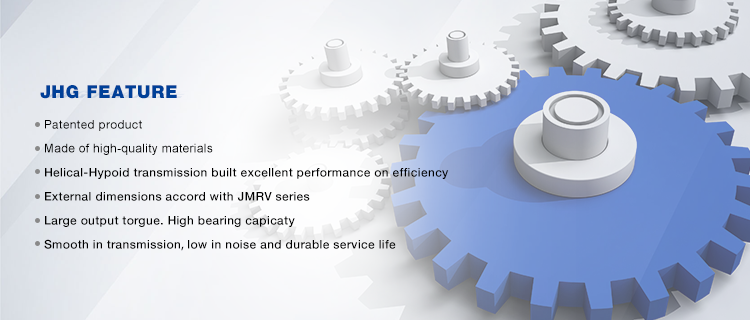
1. Features:
1. High efficiency: 92%-97%;
2. Compact structure: Small offset output, two stage and three stage are in the same box.
3. High precision: the gear is made of high-quality alloy steel forging, carbonitriding and hardening treatment, grinding process to ensure high precision and stable running.
4. High interchangeability: highly modular, serial design, strong versatility and interchangeability.
2. Technical parameters
| Ratio | 3.41-289.74 |
| Input power | 0.12-160KW |
| Output torque | 61-23200N.m |
| Output speed | 5-415rpm |
| Mounting type | Foot mounted, flange mounted, foot and flange mounted, single-stage foot mounted, CZPT flange mounted, Flange-mounted with extended bearing hub |
| Input Method | Flange input(AM), shaft input(AD), inline AC motor input, or AQA servo motor |
| Brake Release | HF-manual release(lock in the brake release position), HR-manual release(autom-atic braking position) |
| Thermistor | TF(Thermistor protection PTC thermisto) TH(Thermistor protection Bimetal swotch) |
| Mounting Position | M1, M2, M3, M4, M5, M6 |
| Type | R17-R167 |
| Output shaft dis. | 20mm, 25mm, 30mm, 35mm, 40mm, 50mm, 60mm, 70mm, 90mm, 110mm, 120mm |
| Housing material | HT200 high-strength cast iron from R37,47,57,67,77,87 |
| Housing material | HT250 High strength cast iron from R97 107,137,147,157,167,187 |
| Heat treatment technology | carbonitriding and hardening treatment |
| Efficiency | 92%-97% |
| Lubricant | VG220 |
| Protection Class | IP55, F class |
Starshine Drive
ZheJiang CZPT Drive Co.,Ltd,the predecessor was a state-owned military mould enterprise, was established in 1965. CZPT specializes in the complete power transmission solution for high-end equipment manufacturing industries based on the aim of “Platform Product, Application Design and Professional Service”.
Starshine have a strong technical force with over 350 employees at present, including over 30 engineering technicians, 30 quality inspectors, covering an area of 80000 square CZPT and kinds of advanced processing machines and testing equipments. We have a good foundation for the industry application development and service of high-end speed reducers & variators owning to the provincial engineering technology research center,the lab of gear speed reducers, and the base of modern R&D.
Our Team
Quality Control
Quality:Insist on Improvement,Strive for Excellence With the development of equipment manufacturing indurstry,customer never satirsfy with the current quality of our products,on the contrary,wcreate the value of quality.
Quality policy:to enhance the overall level in the field of power transmission
Quality View:Continuous Improvement , pursuit of excellence
Quality Philosophy:Quality creates value
3. Incoming Quality Control
To establish the AQL acceptable level of incoming material control, to provide the material for the whole inspection, sampling, immunity. On the acceptance of qualified products to warehousing, substandard goods to take return, check, rework, rework inspection; responsible for tracking bad, to monitor the supplier to take corrective
measures to prevent recurrence.
4. Process Quality Control
The manufacturing site of the first examination, inspection and final inspection, sampling according to the requirements of some projects, judging the quality change trend;
found abnormal phenomenon of manufacturing, and supervise the production department to improve, eliminate the abnormal phenomenon or state.
5. FQC(Final QC)
After the manufacturing department will complete the product, stand in the customer’s position on the finished product quality verification, in order to ensure the quality of
customer expectations and needs.
6. OQC(Outgoing QC)
After the product sample inspection to determine the qualified, allowing storage, but when the finished product from the warehouse before the formal delivery of the goods, there is a check, this is called the shipment inspection.Check content:In the warehouse storage and transfer status to confirm, while confirming the delivery of the
product is a product inspection to determine the qualified products.
7. Certification.
Packing
Delivery
| Application: | Motor, Machinery, Agricultural Machinery |
|---|---|
| Function: | Distribution Power, Change Drive Torque, Change Drive Direction, Speed Changing, Speed Reduction |
| Layout: | Coaxial |
| Hardness: | Hardened Tooth Surface |
| Installation: | Horizontal Type |
| Step: | Three-Step |
| Customization: |
Available
| Customized Request |
|---|

Hypoid Bevel Vs Straight Spiral Bevel – What’s the Difference?
Spiral gears come in many different varieties, but there is a fundamental difference between a Hypoid bevel gear and a Straight spiral bevel. This article will describe the differences between the two types of gears and discuss their use. Whether the gears are used in industrial applications or at home, it is vital to understand what each type does and why it is important. Ultimately, your final product will depend on these differences.
Hypoid bevel gears
In automotive use, hypoid bevel gears are used in the differential, which allows the wheels to rotate at different speeds while maintaining the vehicle’s handling. This gearbox assembly consists of a ring gear and pinion mounted on a carrier with other bevel gears. These gears are also widely used in heavy equipment, auxiliary units, and the aviation industry. Listed below are some common applications of hypoid bevel gears.
For automotive applications, hypoid gears are commonly used in rear axles, especially on large trucks. Their distinctive shape allows the driveshaft to be located deeper in the vehicle, thus lowering the center of gravity and minimizing interior disruption. This design makes the hypoid gearset one of the most efficient types of gearboxes on the market. In addition to their superior efficiency, hypoid gears are very easy to maintain, as their mesh is based on sliding action.
The face-hobbed hypoid gears have a characteristic epicycloidal lead curve along their lengthwise axis. The most common grinding method for hypoid gears is the Semi-Completing process, which uses a cup-shaped grinding wheel to replace the lead curve with a circular arc. However, this method has a significant drawback – it produces non-uniform stock removal. Furthermore, the grinding wheel cannot finish all the surface of the tooth.
The advantages of a hypoid gear over a spiral bevel gear include a higher contact ratio and a higher transmission torque. These gears are primarily used in automobile drive systems, where the ratio of a single pair of hypoid gears is the highest. The hypoid gear can be heat-treated to increase durability and reduce friction, making it an ideal choice for applications where speed and efficiency are critical.
The same technique used in spiral bevel gears can also be used for hypoid bevel gears. This machining technique involves two-cut roughing followed by one-cut finishing. The pitch diameter of hypoid gears is up to 2500 mm. It is possible to combine the roughing and finishing operations using the same cutter, but the two-cut machining process is recommended for hypoid gears.
The advantages of hypoid gearing over spiral bevel gears are primarily based on precision. Using a hypoid gear with only three arc minutes of backlash is more efficient than a spiral bevel gear that requires six arc minutes of backlash. This makes hypoid gears a more viable choice in the motion control market. However, some people may argue that hypoid gears are not practical for automobile assemblies.
Hypoid gears have a unique shape – a cone that has teeth that are not parallel. Their pitch surface consists of two surfaces – a conical surface and a line-contacting surface of revolution. An inscribed cone is a common substitute for the line-contact surface of hypoid bevel gears, and it features point-contacts instead of lines. Developed in the early 1920s, hypoid bevel gears are still used in heavy truck drive trains. As they grow in popularity, they are also seeing increasing use in the industrial power transmission and motion control industries.
Straight spiral bevel gears
There are many differences between spiral bevel gears and the traditional, non-spiral types. Spiral bevel gears are always crowned and never conjugated, which limits the distribution of contact stress. The helical shape of the bevel gear is also a factor of design, as is its length. The helical shape has a large number of advantages, however. Listed below are a few of them.
Spiral bevel gears are generally available in pitches ranging from 1.5 to 2500 mm. They are highly efficient and are also available in a wide range of tooth and module combinations. Spiral bevel gears are extremely accurate and durable, and have low helix angles. These properties make them excellent for precision applications. However, some gears are not suitable for all applications. Therefore, you should consider the type of bevel gear you need before purchasing.
Compared to helical gears, straight bevel gears are easier to manufacture. The earliest method used to manufacture these gears was the use of a planer with an indexing head. However, with the development of modern manufacturing processes such as the Revacycle and Coniflex systems, manufacturers have been able to produce these gears more efficiently. Some of these gears are used in windup alarm clocks, washing machines, and screwdrivers. However, they are particularly noisy and are not suitable for automobile use.
A straight bevel gear is the most common type of bevel gear, while a spiral bevel gear has concave teeth. This curved design produces a greater amount of torque and axial thrust than a straight bevel gear. Straight teeth can increase the risk of breaking and overheating equipment and are more prone to breakage. Spiral bevel gears are also more durable and last longer than helical gears.
Spiral and hypoid bevel gears are used for applications with high peripheral speeds and require very low friction. They are recommended for applications where noise levels are essential. Hypoid gears are suitable for applications where they can transmit high torque, although the helical-spiral design is less effective for braking. For this reason, spiral bevel gears and hypoids are generally more expensive. If you are planning to buy a new gear, it is important to know which one will be suitable for the application.
Spiral bevel gears are more expensive than standard bevel gears, and their design is more complex than that of the spiral bevel gear. However, they have the advantage of being simpler to manufacture and are less likely to produce excessive noise and vibration. They also have less teeth to grind, which means that they are not as noisy as the spiral bevel gears. The main benefit of this design is their simplicity, as they can be produced in pairs, which saves money and time.
In most applications, spiral bevel gears have advantages over their straight counterparts. They provide more evenly distributed tooth loads and carry more load without surface fatigue. The spiral angle of the teeth also affects thrust loading. It is possible to make a straight spiral bevel gear with two helical axes, but the difference is the amount of thrust that is applied to each individual tooth. In addition to being stronger, the spiral angle provides the same efficiency as the straight spiral gear.
Hypoid gears
The primary application of hypoid gearboxes is in the automotive industry. They are typically found on the rear axles of passenger cars. The name is derived from the left-hand spiral angle of the pinion and the right-hand spiral angle of the crown. Hypoid gears also benefit from an offset center of gravity, which reduces the interior space of cars. Hypoid gears are also used in heavy trucks and buses, where they can improve fuel efficiency.
The hypoid and spiral bevel gears can be produced by face-hobbing, a process that produces highly accurate and smooth-surfaced parts. This process enables precise flank surfaces and pre-designed ease-off topographies. These processes also enhance the mechanical resistance of the gears by 15 to 20%. Additionally, they can reduce noise and improve mechanical efficiency. In commercial applications, hypoid gears are ideal for ensuring quiet operation.
Conjugated design enables the production of hypoid gearsets with length or profile crowning. Its characteristic makes the gearset insensitive to inaccuracies in the gear housing and load deflections. In addition, crowning allows the manufacturer to adjust the operating displacements to achieve the desired results. These advantages make hypoid gear sets a desirable option for many industries. So, what are the advantages of hypoid gears in spiral gears?
The design of a hypoid gear is similar to that of a conventional bevel gear. Its pitch surfaces are hyperbolic, rather than conical, and the teeth are helical. This configuration also allows the pinion to be larger than an equivalent bevel pinion. The overall design of the hypoid gear allows for large diameter shafts and a large pinion. It can be considered a cross between a bevel gear and a worm drive.
In passenger vehicles, hypoid gears are almost universal. Their smoother operation, increased pinion strength, and reduced weight make them a desirable choice for many vehicle applications. And, a lower vehicle body also lowers the vehicle’s body. These advantages made all major car manufacturers convert to hypoid drive axles. It is worth noting that they are less efficient than their bevel gear counterparts.
The most basic design characteristic of a hypoid gear is that it carries out line contact in the entire area of engagement. In other words, if a pinion and a ring gear rotate with an angular increment, line contact is maintained throughout their entire engagement area. The resulting transmission ratio is equal to the angular increments of the pinion and ring gear. Therefore, hypoid gears are also known as helical gears.
editor by CX 2023-05-16
China factory High Torque High Quality K Series Helical Electric Gear Motor From China top gear
Product Description
Product Description
Product Description
-K Series Helical Bevel Gearbox
Product Features
1. Input mode: Coupled motor, belted motor, input shaft or connection flange.
2. Output: Right angle
3. Compact structure. Rigid tooth face. Carrying greater torque, high loading capacity.
4.High precision gear, ensuring the unit to operate stably, smooth transmission.
5. Low noise, long lifespan. Large overlap coefficient, abrasion resistant.
Product Parameters
1. Technical data
| Size | 38 | 48 | 58 | 68 | 78 | 88 | 98 | 108 | 128 | 158 | 168 | 188 |
| Structure | K KA KF KAF KAZ KAT KAB | |||||||||||
| Input power rating(kw) | 0.18~3 | 0.18~3 | 0.18~5.5 | 0.18~5.5 | 0.37~11 | 0.75~22 | 1.3~30 | 3~45 | 7.5~90 | 11~160 | 11~200 | 18.5~200 |
| Ratio | 5.36~ 106.38 |
5.81~ 131.87 |
6.57~ 145.15 |
7.14~4 4.79 |
7.22~ 192.18 |
7.19~ 197.27 |
8.95~ 175.47 |
8.74~ 141.93 |
8.68~ 146.07 |
12.66~ 150.03 |
17.35~ 164.44 |
17.97~ 178.37 |
| Maximum Torque(N.m) | 200 | 400 | 600 | 820 | 1550 | 2770 | 4300 | 8000 | 13000 | 18000 | 32000 | 50000 |
| Weight | 11 | 20 | 27 | 33 | 57 | 85 | 130 | 250 | 380 | 610 | 1015 | 1700 |
2: Design option
| K series gear units are available in the following designs | |
| KAZ..Y.. | Short-flange-mounted helical-bevel gear units with hollow shaft |
| K…Y… | Foot-mounted helical-bevel gear units with CZPT shaft |
| KAT…Y… | Torque-arm-mounted helical-bevel gear units with hollow shaft |
| KAB…Y… | Foot-mounted helical-bevel gear units with hollow shaft |
| K(KF,KA,KAF,KAB,KAZ)S… | Shaft input helical-bevel gear units |
| KA…Y… | Helical-bevel gear units with hollow shaft |
| KA(K, KF ,KAF, KAB ,KAZ)R..Y… | Combinatorial helical-bevel gear units |
| KF…Y… | Flange-mounted helical-bevel gear units with CZPT shaft |
| KA(K, KF ,KAF ,KAZ)S…R… | Shaft input combinatorial helical-bevel gear units |
| KAF…Y… | Flange-mounted helical-bevel gear units with hollow shaft |
| KA(K, KF ,KAF, KAB ,KAZ)…Y… | When equipping the user’s motor or the special 1 ,the flange is required to be connected |
Materials Data Sheet
|
Housing material |
Grey Cast iron |
|
Housing hardness |
HBS163~255 |
|
Gear material |
20CrMnTi alloy steel |
|
Surface hardness of gears |
HRC58°~62 ° |
|
Gear core hardness |
HRC33~48 |
|
Input / Output shaft material |
40Cr alloy steel |
|
Input / Output shaft hardness |
HRC32~36 |
|
Machining precision of gears |
accurate grinding, 6~5 Grade |
|
Lubricating oil |
GB L-CKC220-460, Shell Omala220-460 |
|
Heat treatment |
tempering, cementiting, quenching, normalizing, etc. |
|
Efficiency |
94%~96% (depends on the transmission stage) |
|
Noise (MAX) |
60~68dB |
|
Temp. rise (MAX) |
40°C |
|
Temp. rise (Oil)(MAX) |
50°C |
|
Vibration |
≤20µm |
|
Backlash |
≤20Arcmin |
|
Brand of bearings |
China top brand bearing, HRB/LYC/ZWZ/C&U. Or other brands requested, SKF, FAG, INA, NSK. |
|
Brand of oil seal |
NAK — ZheJiang or other brands requested |
Detailed Photos
Our process of production
Our product line
Company Profile
Company Profile
Bode was founded in 2007, which is located in HangZhou city, ZHangZhoug province. As 1 professional manufacturer and exporter, we have more than 17 years’ experience in R & D of worm reducer, gear reducer, gearbox , AC motor and relative spare parts. We have factory with advanced production and test equipment, the strong development of team and producing capacity offer our customers with high quality products. Our products widely served to various industries of Metallurgy, Chemicals, lifting, mining, Petroleum, textile, medicine, wooden etc. Main markets: China, Africa, Australia, Vietnam, Turkey, Japan, Korea, Philippines… Welcome to ask us any questions, good offer always for you for long term business.
FAQ
Q1: Are you trading company or manufacturer?
A: We are factory.
Q2: What kinds of gearbox can you produce for us?
A: Main products of our company: R, S, K, F series helical-tooth reducer, RV series worm gear reducer,H Series Parallel Shaft Helical Reduction Gear Box
Q3: Can you make as per custom drawing?
A: Yes, we offer customized service for customers.
Q4: Can we buy 1 pc of each item for quality testing?
A: Yes, we are glad to accept trial order for quality testing.
Q5: What information shall we give before placing a purchase order?
A: a) Type of the gearbox, ratio, input and output type, input flange, mounting position, and motor informationetc.
b) Housing color.
c) Purchase quantity.
d) Other special requirements.
Q6: How long is your delivery time?
A: Generally it is 5-10 days if the goods are in stock. or it is 15-20 days if the goods are not in stock.
Q7: What is your terms of payment ?
A: 30% Advance payment by T/T after signing the contract.70% before delivery
If you are interested in our product, welcome to contact with us.
Our team will do our best to meet your need 🙂
| Application: | Motor, Machinery, Marine, Agricultural Machinery |
|---|---|
| Function: | Distribution Power, Change Drive Torque, Speed Changing, Speed Reduction |
| Layout: | Coaxial |
| Hardness: | Hardened Tooth Surface |
| Installation: | Vertical Type |
| Step: | Three-Step |
| Samples: |
US$ 90/Piece
1 Piece(Min.Order) | |
|---|
| Customization: |
Available
| Customized Request |
|---|
Types of Bevel Gears
Bevel Gears are used in a number of industries. They are used in wheeled excavators, dredges, conveyor belts, mill actuators, and rail transmissions. A bevel gear’s spiral or angled bevel can make it suitable for confined spaces. It is also used in robotics and vertical supports of rolling mills. You can use bevel gears in food processing processes. For more information on bevel gears, read on.
Spiral bevel gear
Spiral bevel gears are used to transmit power between two shafts in a 90-degree orientation. They have curved or oblique teeth and can be fabricated from various metals. Bestagear is one manufacturer specializing in medium to large spiral bevel gears. They are used in the mining, metallurgical, marine, and oil fields. Spiral bevel gears are usually made from steel, aluminum, or phenolic materials.
Spiral bevel gears have many advantages. Their mesh teeth create a less abrupt force transfer. They are incredibly durable and are designed to last a long time. They are also less expensive than other right-angle gears. They also tend to last longer, because they are manufactured in pairs. The spiral bevel gear also reduces noise and vibration from its counterparts. Therefore, if you are in need of a new gear set, spiral bevel gears are the right choice.
The contact between spiral bevel gear teeth occurs along the surface of the gear tooth. The contact follows the Hertz theory of elastic contact. This principle holds for small significant dimensions of the contact area and small relative radii of curvature of the surfaces. In this case, strains and friction are negligible. A spiral bevel gear is a common example of an inverted helical gear. This gear is commonly used in mining equipment.
Spiral bevel gears also have a backlash-absorbing feature. This feature helps secure the thickness of the oil film on the gear surface. The shaft axis, mounting distance, and angle errors all affect the tooth contact on a spiral bevel gear. Adjusting backlash helps to correct these problems. The tolerances shown above are common for bevel gears. In some cases, manufacturers make slight design changes late in the production process, which minimizes the risk to OEMs.
Straight bevel gear
Straight bevel gears are among the easiest types of gears to manufacture. The earliest method used to manufacture straight bevel gears was to use a planer equipped with an indexing head. However, improvements have been made in manufacturing methods after the introduction of the Revacycle system and the Coniflex. The latest technology allows for even more precise manufacturing. Both of these manufacturing methods are used by CZPT. Here are some examples of straight bevel gear manufacturing.
A straight bevel gear is manufactured using two kinds of bevel surfaces, namely, the Gleason method and the Klingelnberg method. Among the two, the Gleason method is the most common. Unlike other types of gear, the CZPT method is not a universal standard. The Gleason system has higher quality gears, since its adoption of tooth crowning is the most effective way to make gears that tolerate even small assembly errors. It also eliminates the stress concentration in the bevelled edges of the teeth.
The gear’s composition depends on the application. When durability is required, a gear is made of cast iron. The pinion is usually three times harder than the gear, which helps balance wear. Other materials, such as carbon steel, are cheaper, but are less resistant to corrosion. Inertia is another critical factor to consider, since heavier gears are more difficult to reverse and stop. Precision requirements may include the gear pitch and diameter, as well as the pressure angle.
Involute geometry of a straight bevel gear is often computed by varying the surface’s normal to the surface. Involute geometry is computed by incorporating the surface coordinates and the theoretical tooth thickness. Using the CMM, the spherical involute surface can be used to determine tooth contact patterns. This method is useful when a roll tester tooling is unavailable, because it can predict the teeth’ contact pattern.
Hypoid bevel gear
Hypoid bevel gears are an efficient and versatile speed reduction solution. Their compact size, high efficiency, low noise and heat generation, and long life make them a popular choice in the power transmission and motion control industries. The following are some of the benefits of hypoid gearing and why you should use it. Listed below are some of the key misperceptions and false assumptions of this gear type. These assumptions may seem counterintuitive at first, but will help you understand what this gear is all about.
The basic concept of hypoid gears is that they use two non-intersecting shafts. The smaller gear shaft is offset from the larger gear shaft, allowing them to mesh without interference and support each other securely. The resulting torque transfer is improved when compared to conventional gear sets. A hypoid bevel gear is used to drive the rear axle of an automobile. It increases the flexibility of machine design and allows the axes to be freely adjusted.
In the first case, the mesh of the two bodies is obtained by fitting the hyperboloidal cutter to the desired gear. Its geometric properties, orientation, and position determine the desired gear. The latter is used if the desired gear is noise-free or is required to reduce vibrations. A hyperboloidal cutter, on the other hand, meshes with two toothed bodies. It is the most efficient option for modeling hypoid gears with noise concerns.
The main difference between hypoid and spiral bevel gears is that the hypoid bevel gear has a larger diameter than its counterparts. They are usually found in 1:1 and 2:1 applications, but some manufacturers also provide higher ratios. A hypoid gearbox can achieve speeds of three thousand rpm. This makes it the preferred choice in a variety of applications. So, if you’re looking for a gearbox with a high efficiency, this is the gear for you.
Addendum and dedendum angles
The addendum and dedendum angles of a bevel gear are used to describe the shape and depth of the teeth of the gear. Each tooth of the gear has a slightly tapered surface that changes in depth. These angles are defined by their addendum and dedendum distances. Addendum angle is the distance between the top land and the bottom surface of the teeth, while dedendum angle is the distance between the pitch surface and the bottom surface of the teeth.
The pitch angle is the angle formed by the apex point of the gear’s pitch cone with the pitch line of the gear shaft. The dedendum angle, on the other hand, is the depth of the tooth space below the pitch line. Both angles are used to measure the shape of a bevel gear. The addendum and dedendum angles are important for gear design.
The dedendum and addendum angles of a bevel gear are determined by the base contact ratio (Mc) of the two gears. The involute curve is not allowed to extend within the base diameter of the bevel gear. The base diameter is also a critical measurement for the design of a gear. It is possible to reduce the involute curve to match the involute curve, but it must be tangential to the involute curve.
The most common application of a bevel gear is the automotive differential. They are used in many types of vehicles, including cars, trucks, and even construction equipment. They are also used in the marine industry and aviation. Aside from these two common uses, there are many other uses for bevel gears. And they are still growing in popularity. But they’re a valuable part of automotive and industrial gearing systems.
Applications of bevel gears
Bevel gears are used in a variety of applications. They are made of various materials depending on their weight, load, and application. For high-load applications, ferrous metals such as grey cast iron are used. These materials have excellent wear resistance and are inexpensive. For lower-weight applications, steel or non-metals such as plastics are used. Some bevel gear materials are considered noiseless. Here are some of their most common uses.
Straight bevel gears are the easiest to manufacture. The earliest method of manufacturing them was with a planer with an indexing head. Modern manufacturing methods introduced the Revacycle and Coniflex systems. For industrial gear manufacturing, the CZPT uses the Revacycle system. However, there are many types of bevel gears. This guide will help you choose the right material for your next project. These materials can withstand high rotational speeds and are very strong.
Bevel gears are most common in automotive and industrial machinery. They connect the driveshaft to the wheels. Some even have a 45-degree bevel. These gears can be placed on a bevel surface and be tested for their transmission capabilities. They are also used in testing applications to ensure proper motion transmission. They can reduce the speed of straight shafts. Bevel gears can be used in many industries, from marine to aviation.
The simplest type of bevel gear is the miter gear, which has a 1:1 ratio. It is used to change the axis of rotation. The shafts of angular miter bevel gears can intersect at any angle, from 45 degrees to 120 degrees. The teeth on the bevel gear can be straight, spiral, or Zerol. And as with the rack and pinion gears, there are different types of bevel gears.
editor by CX 2023-04-24
Best China manufacturer & factory china in Bologna Italy supplier helical worm bucket wheel excavators hydraulic industrial gear reducer motor With high quality best price

Every process, each and every segment, every perform in EPG is demanded to be completed a single phase adhering to an additional, meticulously and cautiously, from content variety, reformation to manufacturing components, from factors warmth treatment to automated assembly, from good quality control to item inspection and tests and from get working to soon after product sales support.
Overview
Rapid Specifics
- Relevant Industries:
-
Producing Plant
- Pole:
-
3 stage four stage six Stage
- Ratio:
-
1:20 1:300
- Housing Substance:
-
Forged Iron / Aluminum casing
- Working temperature:
-
-forty~45℃
- Software:
-
mining, Foods processing creation line conveyor concrete mixers
SFI M100 PTO AdapterAs a precautionary measure, it is a excellent concept to buy a PTO adapter to make sure compatibility with your particular tractor model.
- Process:
-
Carburizing, Nitriding , Grinding
- Efficiency:
-
ninety four%~ninety eight%
- Mounting Place:
-
Horizontal,Vertical,Flange
- Color:
-
Blue,Environmentally friendly,Grey,Purple
- Kind:
-
helical worm excavators hydraulic industrial equipment reducer motor
Packaging & Shipping
-
Lead Time
: -
Amount(Luggage) 1 – ten >10 Est. Time(times) 15 To be negotiated
Online Customization
Greater working temperatures can gradually “cure” and harden seal lips, creating them drop the overall flexibility necessary to seal successfully.
Item Description

Expert MANUFACTURE
—— Because 1995
R series Helical Gear Pace Reducer Gearbox
Hard Tooth Sureface Gear / Helical Gear Box Transmission
helical worm bucket wheel excavators hydraulic industrial equipment reducer motor
Chinese electric motor speed reducer is broadly utilized in mining machinery, chemical market,steel metallurgy, gentle industry,environmental defense, paper creating, printing, lifting transport, food sector and so on.
Primary Series Product: R series helical gearbox reducer, K series spiral bevel equipment reducer, NGW, P sequence planetary reducer, H B collection gearbox, Z (ZDY, ZLY, ZSY, and ZFY) serial hard tooth surface cylindrical gear reducer, D (DBY and DCY) serial hard tooth surface cone equipment reducer, cycloid reducer, etc. In the meantime, map sample processing organization can be undertaken.
Specification
R167 helical worm bucket wheel excavators hydraulic industrial gear reducer motor:
(you should contact us for a lot more sorts & product)
R Series Industrial Helical Equipment Gearbox Electric powered Motor Pace Reducer, Made on the basis of modular mixed technique,the gear reducer have plentiful combos of motor,mounting situation and framework initiatives,the classifying course of transmission ratio is in depth,which is appropriate for diverse working circumstance and recognize mechatronics. R helical worm bucket wheel excavators hydraulic industrial equipment reducer motor.
| Measurement | R17 | R27 | R37 | R47 | R57 | R67 | R77 | R87 | R97 |
| Weight(KG) | four | five.five | 8.5 | 10 | eighteen | 25 | 36 | sixty three | a hundred and one |
| Measurement | R107 | R137 | R147 | R167The business covering 88,000 square meters, has advanced tools and powerful technical strength, these kinds of as the numerical management machine instruments and machining facilities, CAD/CAM technique, industrial robot and so forth. | RX87 | RX97 | RX107 | RX127 | RX157 |
| Weight(KG) | 153 | 220 | 400 | seven-hundred | 39 | 70 | a hundred | one hundred fifty | 250 |
Engineering
Design assortment of helical gearbox Electrical motor velocity reducer:
Carefully using the excellent reduction ratio.
Reduction ratio = servo motor speed / reducer output shaft pace
Torque calculation: Torque calculation is extremely crucial for the life of reducer, and spend interest to whether the maximum torque price (TP) of acceleration exceeds the maximum load torque of the reducer.
The relevant electrical power is usually the relevant electrical power of the servo types on the market place, the applicability of the reducer is quite large, the operating coefficient can be maintained over 1.2, but the option can also be based mostly on their very own wants to choose. helical equipment belt conveyor Gearbox for Mineral market/Foodstuff processing/Drilling/Mixer electric gear velocity reducer reduction coaxial motor with gearbox R helical worm bucket wheel excavators hydraulic industrial gear reducer motor.
Business Data
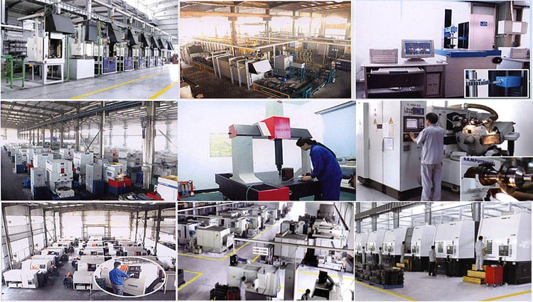
Established in 1995 , HangZhou At any time-Energy Machinery is a specialist producer and exporter that is anxious with the design, advancement and manufacturing of Gearbox Pace Reducer. We are situated in HangZhou of ZheJiang Province, with convenient transportation access. With our possess brand “EPG”, all of our products comply with intercontinental good quality specifications and are drastically appreciated in a assortment of different marketplaces all through the entire world.
Our company possesses complete machining center, lathe, equipment shaping equipment, gear milling device, equipment grinding device and assembling traces. Our well-geared up amenities and excellent top quality handle throughout all phases of production enables us to ensure total buyer pleasure.
Besides, In 2005,we attained ISO9001 certification. As a result of our higher high quality items and exceptional client provider, we have obtained a global income network reaching South The us, Saudi Arabia, Vietnam, Pakistan, Philippines, South Africa and other international locations and regions.
With wealthy export knowledge, high quality products, competitive prices, great support and in-time delivery, we specific that we can fulfill all of your requirement and exceed your anticipations. Our characteristic is vibrant with new cooperative associations with businesses from all over the entire world. We appear ahead to talking with you to future discuss how we can be of support to you.
Major Merchandise
Our Principal Products:
- R series helical equipment motor gearbox reducer
- K series spiral bevel gear reducer
- F series parallel shadt equipment motor reducer
- S series worm gear reducer motor gearbox
- NGW, P series planetary gear box reducer
- H B series gearbox
- Z (ZDY, ZLY, ZSY, and ZFY) serial hard tooth surface cylindrical gearbox
- D (DBY and DCY) serial hard tooth surface cone gearbox
- X B Seires cycloidal gearbox reducer
- ZLYJ Extruder Gearbox, etc.
Meanwhile, map sample processing company can be carried out.
Our Solutions
Chinese Helical Gearbox With 22kw A few Phase Motor Electric Motor Pace Reducer is a mechanical transmission in a lot of fields of the nationwide economic system. The item types protected by the sector include all sorts of gear reducer, planetary equipment reducer and worm gearbox, as nicely as different particular transmission gadgets such as speed growing device, pace management Gadgets, such as different types of flexible transmission units, this kind of as compound transmission. Items and services in the discipline of metallurgy, nonferrous metals, coal, building supplies, ships, drinking water conservancy, electricity, design machinery and petrochemical industries.
In all fields of nationwide economy and nationwide defense industry, gearbox products have a extensive variety of programs. Food gentle sector, electrical machinery, building equipment, metallurgy machinery, cement machinery, environmental security equipment, digital appliances, road building machinery, water conservancy machinery, chemical machinery, mining equipment, conveyor equipment, constructing components machinery, rubber equipment, petroleum machinery and other industries have sturdy need of Reducer products. R137 -Y22-4P-M1 sequence Helical equipment helical Gearbox with 22KW motor.
Packaging & Shipping and delivery
FAQ
1.Q:Are you the manufacturing facility or buying and selling company?
A:We are the expert Manufacturing facility with above twenty five years of experience.
two.Q:Can you customise according to our requirements?
A:Sure, we can layout nonstandard merchandise in accordance to customer’s drawing and sample.
three.Q:How extended is the shipping day?
A:10-20 doing work times.
four.Q:In which is your manufacturing unit?
A:We are in HangZhou of ZheJiang Province, you can get below by higher velocity train or fly to Jinan.
Welcome to visit us!
5.Q:What’s your payment terms?
A:TT thirty% as deposite, 70% banlance compensated ahead of supply.