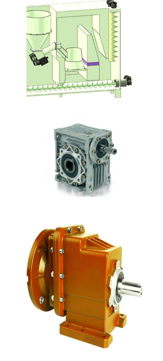
Product Description
1) According to the various toughness and performance, we select the metal with sturdy compression
two) Using Germany professional application and our professional engineers to design goods with more realistic measurement and much better efficiency 3) We can customise our goods in accordance to the needs of our customers,As a result, the ideal efficiency of the gear can be exerted beneath different doing work circumstances
4) Quality assurance in each and every step to guarantee item top quality is controllable.
Merchandise Paramenters
| Pushed Gear |
Amount OF Tooth |
ten |
|
MODULE |
twelve.35 | |
|
LENTH |
303 | |
|
OUTER DIAMETER |
ø175.two |
|
|
Direction OF SPIRAL |
L |
|
|
Precision OF SPLINE |
M33*1.5-6h | |
|
Number OF SPLINE |
42 |
|
DRIVEN Gear |
Quantity OF Enamel |
37 |
|
OUTER DIAMETER |
ø456.nine |
|
|
DIAMETER OF Internal Gap |
ø260 |
|
|
Accuracy OF SCREW |
12-M20*1.5-6H | |
|
Centre Length OF SCREW Hole |
ø340 |
|
|
Direction OF SPIRAL |
R |
Company Profiles
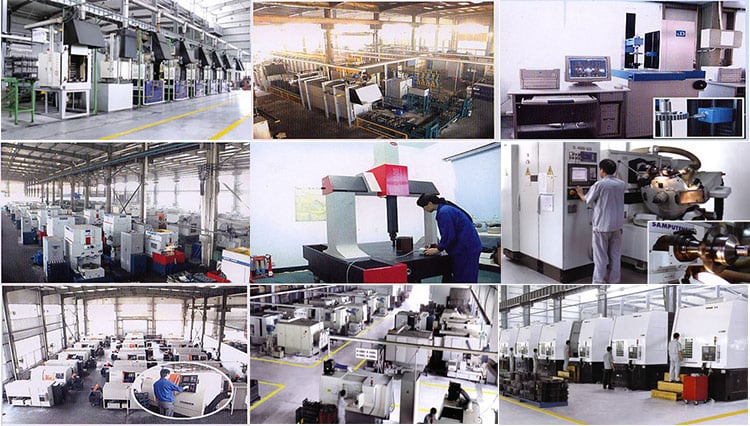
Our business,HangZhou CZPT Equipment co.,Ltd , specialized in Hypoid and spiral bevel equipment utilized in Automotive sector, was foundeded in 1996, with registered money 136,8 square meter, with creating location of 72,000 square meters. More than 500 employees perform in our firm.
We personal a lot more than 560 higher-exact machining equipments, 10 Klingelnberg Oerlikon gear generation strains, 36 Gleason equipment creation traces, 5 forging production traces 2 german Aichilin and 5 CZPT CZPT sophisticated automatic continuous heat therapy generation lines. With the introducing the innovative Oerlikon C50 and P65 measuring center, we enhence our engineering degree and boost our product high quality a great deal. We offer you greater top quality and very good after-sale provider with low cost, which insure the very good status. With the principle of “for the men and women, by technologies, creativeness, for the society, transfering friendship, truthful”, we are making an attempt to provice the globe-best level product.
Our aim is: CZPT Equipment,planet course, Push the globe.
In accordance to the distinct power and performance, we choose the metal with powerful compressionUsing Germany professional computer software and our specialist engineers to design and style goods with much more reasonable size and better performanceWe can personalize our items according to the wants of our buyers,Therefore, the best functionality of the equipment can be exerted beneath distinct operating conditionsQuality assurance in every step to make sure solution top quality is controllable.
Our firm had complete quality administration program and experienced been certified by ISO9001:2000, QS-9000:1998, ISO/TS16949 , which insure the entrance of worldwide marketplace.
Certification & honors
Packaging & Shipping
Packaging Depth:regular deal(carton ,wood pallet).
Transport:Support Sea freight. Accept FOB,EXW,FAS,DES.
Cooperative clients
HangZhou CZPT Gear Co., Ltd. adheres to the idea of “folks-oriented, prosper with science and engineering develop substantial-high quality goods, lead to the society turn friendship, and contribute sincerely”, and will try to develop world automotive axle spiral bevel equipment goods.
one.Do you provide samples?
Of course,we can provide free sample but not pay the cost of freight.
two.What about OEM?
Indeed,we can do OEM in accordance to your demands.
3.How about soon after-income service?
We have exceptional right after-revenue support if you have any quanlity issue,you can make contact with us whenever.
four.What about package?
Stardard package deal or tailored deal as specifications.
five.How to guarantee the quanlity of the merchandise?
We can offer uncooked meterial report,metallographic assessment and the precision screening and so on.
six.How extended is your shipping and delivery time?
Genarally it is 4-7 days.If personalized it will be get 20 times in accordance to your amount.
|
/ Set | |
1 Set (Min. Order) |
###
| Application: | Motor, Electric Cars, Motorcycle, Machinery, Marine, Agricultural Machinery, Car |
|---|---|
| Hardness: | Hardened Tooth Surface |
| Gear Position: | External Gear |
| Manufacturing Method: | Cast Gear |
| Toothed Portion Shape: | Herringbone Gear |
| Material: | Cast Steel |
###
| Samples: |
US$ 80/Set
1 Set(Min.Order) |
|---|
###
| Customization: |
|---|
###
| DRIVEN GEAR |
NUMBER OF TEETH
|
10
|
|
MODULE
|
12.35 | |
|
LENTH
|
303 | |
|
OUTER DIAMETER
|
ø175.2
|
|
|
DIRECTION OF SPIRAL
|
L
|
|
|
ACCURACY OF SPLINE
|
M33*1.5-6h | |
|
NUMBER OF SPLINE
|
42
|
###
|
DRIVEN GEAR
|
NUMBER OF TEETH
|
37
|
|
OUTER DIAMETER
|
ø456.9
|
|
|
DIAMETER OF INNER HOLE
|
ø260
|
|
|
ACCURACY OF SCREW
|
12-M20*1.5-6H | |
|
CENTER DISTANCE OF SCREW HOLE
|
ø340
|
|
|
DIRECTION OF SPIRAL
|
R
|
|
/ Set | |
1 Set (Min. Order) |
###
| Application: | Motor, Electric Cars, Motorcycle, Machinery, Marine, Agricultural Machinery, Car |
|---|---|
| Hardness: | Hardened Tooth Surface |
| Gear Position: | External Gear |
| Manufacturing Method: | Cast Gear |
| Toothed Portion Shape: | Herringbone Gear |
| Material: | Cast Steel |
###
| Samples: |
US$ 80/Set
1 Set(Min.Order) |
|---|
###
| Customization: |
|---|
###
| DRIVEN GEAR |
NUMBER OF TEETH
|
10
|
|
MODULE
|
12.35 | |
|
LENTH
|
303 | |
|
OUTER DIAMETER
|
ø175.2
|
|
|
DIRECTION OF SPIRAL
|
L
|
|
|
ACCURACY OF SPLINE
|
M33*1.5-6h | |
|
NUMBER OF SPLINE
|
42
|
###
|
DRIVEN GEAR
|
NUMBER OF TEETH
|
37
|
|
OUTER DIAMETER
|
ø456.9
|
|
|
DIAMETER OF INNER HOLE
|
ø260
|
|
|
ACCURACY OF SCREW
|
12-M20*1.5-6H | |
|
CENTER DISTANCE OF SCREW HOLE
|
ø340
|
|
|
DIRECTION OF SPIRAL
|
R
|
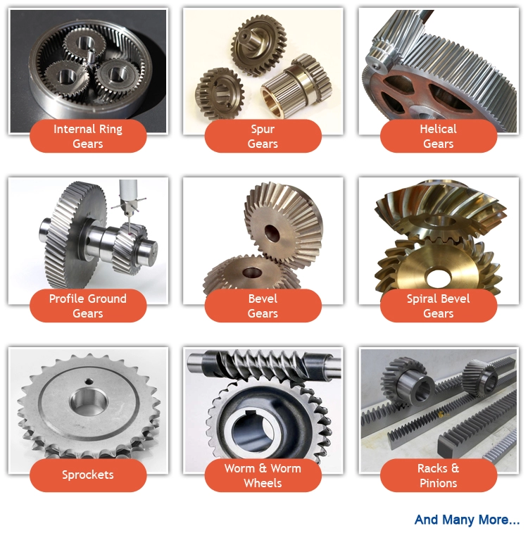
Types of Bevel Gears
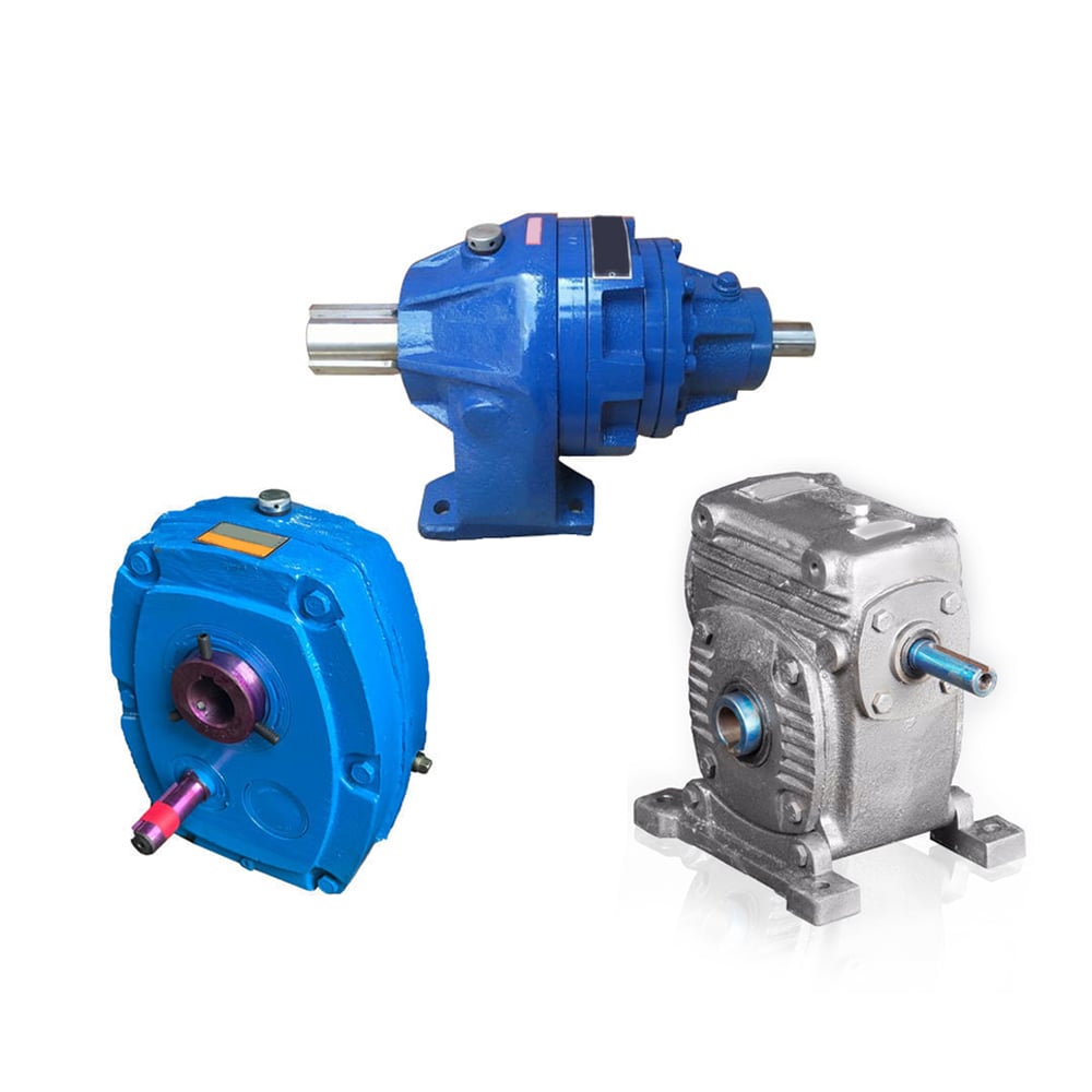
Bevel Gears are used in a number of industries. They are used in wheeled excavators, dredges, conveyor belts, mill actuators, and rail transmissions. A bevel gear’s spiral or angled bevel can make it suitable for confined spaces. It is also used in robotics and vertical supports of rolling mills. You can use bevel gears in food processing processes. For more information on bevel gears, read on.
Spiral bevel gear
Spiral bevel gears are used to transmit power between two shafts in a 90-degree orientation. They have curved or oblique teeth and can be fabricated from various metals. Bestagear is one manufacturer specializing in medium to large spiral bevel gears. They are used in the mining, metallurgical, marine, and oil fields. Spiral bevel gears are usually made from steel, aluminum, or phenolic materials.
Spiral bevel gears have many advantages. Their mesh teeth create a less abrupt force transfer. They are incredibly durable and are designed to last a long time. They are also less expensive than other right-angle gears. They also tend to last longer, because they are manufactured in pairs. The spiral bevel gear also reduces noise and vibration from its counterparts. Therefore, if you are in need of a new gear set, spiral bevel gears are the right choice.
The contact between spiral bevel gear teeth occurs along the surface of the gear tooth. The contact follows the Hertz theory of elastic contact. This principle holds for small significant dimensions of the contact area and small relative radii of curvature of the surfaces. In this case, strains and friction are negligible. A spiral bevel gear is a common example of an inverted helical gear. This gear is commonly used in mining equipment.
Spiral bevel gears also have a backlash-absorbing feature. This feature helps secure the thickness of the oil film on the gear surface. The shaft axis, mounting distance, and angle errors all affect the tooth contact on a spiral bevel gear. Adjusting backlash helps to correct these problems. The tolerances shown above are common for bevel gears. In some cases, manufacturers make slight design changes late in the production process, which minimizes the risk to OEMs.
Straight bevel gear
Straight bevel gears are among the easiest types of gears to manufacture. The earliest method used to manufacture straight bevel gears was to use a planer equipped with an indexing head. However, improvements have been made in manufacturing methods after the introduction of the Revacycle system and the Coniflex. The latest technology allows for even more precise manufacturing. Both of these manufacturing methods are used by CZPT. Here are some examples of straight bevel gear manufacturing.
A straight bevel gear is manufactured using two kinds of bevel surfaces, namely, the Gleason method and the Klingelnberg method. Among the two, the Gleason method is the most common. Unlike other types of gear, the CZPT method is not a universal standard. The Gleason system has higher quality gears, since its adoption of tooth crowning is the most effective way to make gears that tolerate even small assembly errors. It also eliminates the stress concentration in the bevelled edges of the teeth.
The gear’s composition depends on the application. When durability is required, a gear is made of cast iron. The pinion is usually three times harder than the gear, which helps balance wear. Other materials, such as carbon steel, are cheaper, but are less resistant to corrosion. Inertia is another critical factor to consider, since heavier gears are more difficult to reverse and stop. Precision requirements may include the gear pitch and diameter, as well as the pressure angle.
Involute geometry of a straight bevel gear is often computed by varying the surface’s normal to the surface. Involute geometry is computed by incorporating the surface coordinates and the theoretical tooth thickness. Using the CMM, the spherical involute surface can be used to determine tooth contact patterns. This method is useful when a roll tester tooling is unavailable, because it can predict the teeth’ contact pattern.
Hypoid bevel gear
Hypoid bevel gears are an efficient and versatile speed reduction solution. Their compact size, high efficiency, low noise and heat generation, and long life make them a popular choice in the power transmission and motion control industries. The following are some of the benefits of hypoid gearing and why you should use it. Listed below are some of the key misperceptions and false assumptions of this gear type. These assumptions may seem counterintuitive at first, but will help you understand what this gear is all about.
The basic concept of hypoid gears is that they use two non-intersecting shafts. The smaller gear shaft is offset from the larger gear shaft, allowing them to mesh without interference and support each other securely. The resulting torque transfer is improved when compared to conventional gear sets. A hypoid bevel gear is used to drive the rear axle of an automobile. It increases the flexibility of machine design and allows the axes to be freely adjusted.
In the first case, the mesh of the two bodies is obtained by fitting the hyperboloidal cutter to the desired gear. Its geometric properties, orientation, and position determine the desired gear. The latter is used if the desired gear is noise-free or is required to reduce vibrations. A hyperboloidal cutter, on the other hand, meshes with two toothed bodies. It is the most efficient option for modeling hypoid gears with noise concerns.
The main difference between hypoid and spiral bevel gears is that the hypoid bevel gear has a larger diameter than its counterparts. They are usually found in 1:1 and 2:1 applications, but some manufacturers also provide higher ratios. A hypoid gearbox can achieve speeds of three thousand rpm. This makes it the preferred choice in a variety of applications. So, if you’re looking for a gearbox with a high efficiency, this is the gear for you.
Addendum and dedendum angles
The addendum and dedendum angles of a bevel gear are used to describe the shape and depth of the teeth of the gear. Each tooth of the gear has a slightly tapered surface that changes in depth. These angles are defined by their addendum and dedendum distances. Addendum angle is the distance between the top land and the bottom surface of the teeth, while dedendum angle is the distance between the pitch surface and the bottom surface of the teeth.
The pitch angle is the angle formed by the apex point of the gear’s pitch cone with the pitch line of the gear shaft. The dedendum angle, on the other hand, is the depth of the tooth space below the pitch line. Both angles are used to measure the shape of a bevel gear. The addendum and dedendum angles are important for gear design.
The dedendum and addendum angles of a bevel gear are determined by the base contact ratio (Mc) of the two gears. The involute curve is not allowed to extend within the base diameter of the bevel gear. The base diameter is also a critical measurement for the design of a gear. It is possible to reduce the involute curve to match the involute curve, but it must be tangential to the involute curve.
The most common application of a bevel gear is the automotive differential. They are used in many types of vehicles, including cars, trucks, and even construction equipment. They are also used in the marine industry and aviation. Aside from these two common uses, there are many other uses for bevel gears. And they are still growing in popularity. But they’re a valuable part of automotive and industrial gearing systems.
Applications of bevel gears
Bevel gears are used in a variety of applications. They are made of various materials depending on their weight, load, and application. For high-load applications, ferrous metals such as grey cast iron are used. These materials have excellent wear resistance and are inexpensive. For lower-weight applications, steel or non-metals such as plastics are used. Some bevel gear materials are considered noiseless. Here are some of their most common uses.
Straight bevel gears are the easiest to manufacture. The earliest method of manufacturing them was with a planer with an indexing head. Modern manufacturing methods introduced the Revacycle and Coniflex systems. For industrial gear manufacturing, the CZPT uses the Revacycle system. However, there are many types of bevel gears. This guide will help you choose the right material for your next project. These materials can withstand high rotational speeds and are very strong.
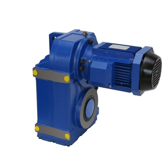
Bevel gears are most common in automotive and industrial machinery. They connect the driveshaft to the wheels. Some even have a 45-degree bevel. These gears can be placed on a bevel surface and be tested for their transmission capabilities. They are also used in testing applications to ensure proper motion transmission. They can reduce the speed of straight shafts. Bevel gears can be used in many industries, from marine to aviation.
The simplest type of bevel gear is the miter gear, which has a 1:1 ratio. It is used to change the axis of rotation. The shafts of angular miter bevel gears can intersect at any angle, from 45 degrees to 120 degrees. The teeth on the bevel gear can be straight, spiral, or Zerol. And as with the rack and pinion gears, there are different types of bevel gears.


editor by CX 2023-03-27